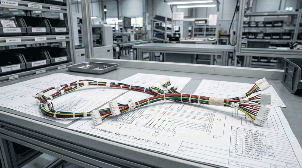
Patient Monitoring Cable Assemblies
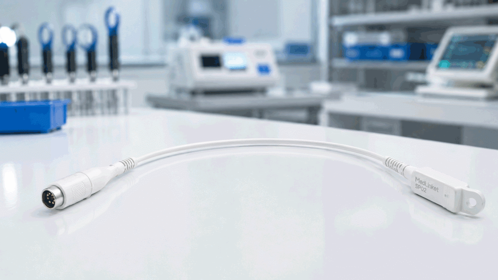
Patient monitoring cable assemblies are used in equipment where signal stability, repeated handling, compact routing, and connector reliability are critical. In patient monitors, portable healthcare devices, vital signs equipment, and related medical electronics, a cable assembly may connect sensors, displays, power modules, communication boards, batteries, and internal control systems.
For OEM buyers, these cables are not simply standard wires with connectors attached. A monitoring device may operate for long periods, move between rooms, be handled by different users, or include several internal modules inside a compact enclosure. The wiring harness must fit the available space, support stable electrical performance, and remain reliable during repeated use.
Some monitoring cable assemblies are installed permanently inside the equipment. Others may move with a hinged display, removable module, battery pack, or service panel. External cables may face repeated bending and pulling, while internal wire harnesses may need precise routing around boards, fans, batteries, and display modules.
The supplier therefore needs to understand more than connector type and cable length. Application, movement, signal type, installation space, maintenance requirements, testing, and expected production volume all affect the final design.
This article explains the main considerations for OEM buyers sourcing patient monitoring cable assemblies and custom wiring harnesses for healthcare-related devices.
Table of Contents
ToggleMonitoring Equipment Needs Stable Connections
Patient monitoring equipment depends on continuous and reliable electrical connections. A cable assembly problem may appear as an intermittent signal, communication error, display issue, unexpected restart, or unstable measurement. These failures are often more difficult to diagnose than a completely open circuit.
An intermittent connection may work during factory testing and fail only after repeated movement or installation. A terminal may be seated incorrectly but still make temporary contact. A wire may be stressed at the connector exit and fail after repeated bending. A shielding connection may be inconsistent, creating noise in a sensitive signal path.
For this reason, monitoring cable assemblies need repeatable manufacturing and inspection. Connector assembly, terminal crimping, wire preparation, strain relief, and routing should all follow controlled instructions.
The supplier should also understand where the cable is used. A power harness inside the device has different requirements from a cable carrying sensor or communication signals. A harness connected to a moving display may require different flexibility from a fixed internal cable.
The more clearly the application is defined, the easier it is to select the correct wire, protection, connector, and test method.
Internal and External Cables
Patient monitoring devices may use both internal wire harnesses and external cable assemblies. These two groups often have different requirements.
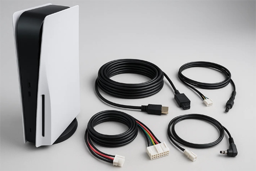
Internal harnesses connect PCBs, displays, batteries, fans, power modules, communication boards, buttons, and other internal components. Space is often limited, so cable routing must be controlled carefully. The harness may need short branches, small connectors, thin wires, specific exit directions, or labels that help assembly workers identify each connection.
External cable assemblies face different mechanical conditions. They may be handled frequently, bent, pulled, cleaned, stored, or moved with the equipment. The cable jacket, strain relief, connector locking, and flexibility become more important.
OEM buyers should clearly tell the supplier whether the assembly is internal or external. A supplier should not assume that the same materials and construction are suitable for both applications.
For internal cables, compact routing and assembly consistency may be the priority. For external cables, repeated bending, handling, cable jacket performance, and connector durability may require more attention.
Signal Stability
Patient monitoring systems may carry sensor data, communication signals, power, or control circuits. Some signals can be sensitive to electrical noise or inconsistent connections.
Signal stability depends on several factors. Wire type, shielding, twisted pairs, grounding, connector quality, and routing can all affect performance. A cable assembly that passes continuity testing may still create problems if it is not suitable for the signal it carries.
For example, a low-level sensor circuit may require better noise control than a simple power connection. Communication lines may need controlled wire pairing or shielding. Mixed power and signal circuits inside the same harness may require careful routing.
The supplier needs to know the signal type. A drawing that only shows Pin 1 to Pin 1 and Pin 2 to Pin 2 may be enough to build a physically correct cable, but it does not explain the electrical function.
OEM buyers do not always need to share confidential system details. However, basic information such as power, sensor signal, communication, or mixed circuit helps the cable assembly manufacturer make better manufacturing and material decisions.
If the customer has experienced noise, intermittent readings, or communication instability, this information should be shared during RFQ review. The problem may relate to shielding, grounding, connector contact, cable routing, or repeated mechanical stress.
Flexing and Repeated Movement
Repeated movement is a major consideration in monitoring equipment. A cable may move when a display is adjusted, a battery door is opened, a module is removed, or the device is transported.
A standard wire may work well in a fixed installation but fail earlier when repeatedly bent. The cable exit point is often the highest-risk area. If the wire bends sharply next to the connector or terminal, repeated stress can damage the conductor.
Strain relief helps distribute mechanical load. This may include molded strain relief, heat shrink, flexible tubing, boots, clamps, or controlled cable routing. The correct solution depends on the product design.
Bend radius should also be considered. A cable forced around a tight internal corner may experience continuous stress. In compact monitoring devices, engineering teams sometimes focus on PCB and enclosure layout first and leave little space for cable routing. The harness then becomes difficult to install.
Testing the first cable assembly inside the actual device is important. The OEM should check whether the cable bends naturally, whether the connector exit is under stress, and whether movement creates tension on the terminals.
Small changes in cable length or exit direction can sometimes improve reliability significantly.
Compact Device Routing
Portable monitors and compact healthcare devices often have limited internal space. Cables may need to route between PCBs, displays, batteries, speakers, fans, and enclosure features.
In this environment, a cable that is only slightly too long may create a large loop that interferes with assembly. A cable that is too short may pull on the connector. A stiff cable may push against a PCB or enclosure panel.
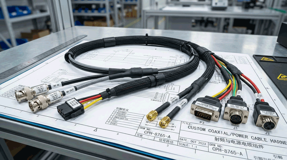
Branch location also matters. In a multi-branch wiring harness, the breakout position should match the device layout. If the branch point is not controlled, production workers may route each harness differently.
Connector orientation is another important detail. Some compact connectors can be installed in several physical directions during harness assembly, but only one orientation works efficiently inside the equipment. The drawing should show connector orientation clearly when it affects installation.
OEM buyers should provide enclosure layouts, photos, samples, or installation feedback when possible. A cable assembly supplier cannot always understand space limitations from a simple schematic.
Prototype builds are useful for this reason. The first samples can be installed and reviewed before the design is frozen.
Connector Reliability
Connectors in patient monitoring equipment need stable mating and consistent terminal retention. Internal connectors may be connected during assembly and remain in place for years. Service connectors may be disconnected during repair. External connectors may face much more frequent handling.
The connector choice should match the use pattern. A connector used inside a fixed enclosure may not require the same locking system as an external service cable. A removable battery module may require connectors designed for repeated mating. A moving assembly may need better retention to prevent vibration or movement from loosening the connection.
Terminal crimping is equally important. A good connector housing cannot compensate for a poor crimp. Crimp height, conductor position, insulation support, terminal damage, and wire preparation all affect the connection.
Small-pitch connectors can be especially sensitive because the terminals are small and difficult to inspect visually. The supplier should use suitable tooling and inspection methods.
Connector availability should also be reviewed early. If an OEM design uses a hard-to-source connector, sample and production lead time may become unpredictable. For new products, engineering teams may want to consider connector availability before the design is fully frozen.
For existing devices or replacement projects, exact mating compatibility may be required.
Cable Jacket and Wire Choice
Material selection should be based on the actual use environment. There is no single wire or cable jacket that is best for every monitoring device.
Internal harnesses may use standard insulated wires when the cables are protected inside the enclosure. External cables may need softer jackets, better flexibility, abrasion resistance, or resistance to repeated cleaning.
Temperature requirements should also be considered. Even if the equipment operates in a normal room environment, internal electronic components can create local heat. Battery modules, power supplies, and processing boards may increase temperature near the harness.
Wire gauge should match current and voltage requirements. Using larger wire does not automatically create a better design. A wire that is too large may be difficult to route and may not fit the connector terminal correctly. A wire that is too small may create voltage drop or heat.
For signal circuits, conductor construction and shielding may be more important than current capacity.
The OEM should provide wire specifications when they are already defined. If not, the supplier needs application information to recommend or quote a suitable option.
Shielding and Grounding
Some patient monitoring cable assemblies may require shielding to reduce interference. Shielding is common in noise-sensitive systems, but the design should be based on the actual electrical requirement.
A shielded cable includes more than a shield layer. The way the shield is terminated also matters. The shield may connect through a drain wire, connector shell, ground terminal, or another method defined by the equipment design.
Incorrect shield termination can reduce performance. Inconsistent shield handling during production may also create variation between batches.
The drawing should show how the shield is prepared and connected. If the shield is connected at only one end, this should be clearly documented. If the connector shell is part of the grounding method, the supplier needs to understand the assembly requirement.
Shielding also affects manufacturing. Preparing braid, foil, or drain wires adds process steps. Heat shrink, soldering, crimp sleeves, or shield clamps may be required.
For OEM buyers, shielding requirements should be confirmed before quotation because they affect material, labor, testing, and lead time.
Strain Relief
Strain relief is particularly important where cables exit connectors, enclosures, or moving modules. Repeated pulling or bending can transfer stress directly to the conductor or terminal if the cable is not supported.
There are several strain relief methods. Heat shrink can provide basic support and transition. Molded strain relief can control the cable exit and improve mechanical protection. Flexible tubing or boots can reduce sharp bending. Internal clamps can prevent cable movement from reaching the connector.
The correct design depends on the movement and available space.
A common mistake is making strain relief too rigid. If the protected section is very stiff and ends suddenly, the bending stress may move to the point immediately after the strain relief. A gradual transition is often more suitable for cables that move repeatedly.
OEM buyers should review damaged field cables carefully. The failure location can reveal where stress is concentrated. If multiple cables fail near the same connector or exit point, replacing the cable without reviewing strain relief may repeat the problem.
Labels and Assembly Control
Patient monitoring equipment may contain several similar internal cable assemblies. During production, clear identification can reduce connection mistakes.
Labels can show part numbers, connector names, branch identification, revision, or installation location. Wire colors can also support assembly control, but color alone should not replace a controlled pinout.
The label position should be practical. A label hidden after installation may not help service technicians. A label too close to a bend may become damaged or difficult to read.
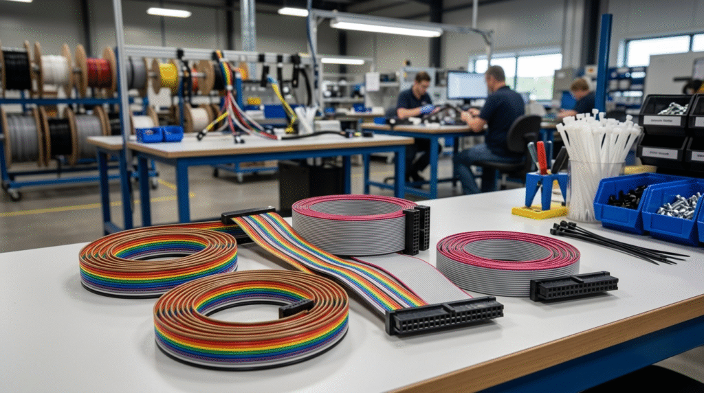
For OEM production, cable assembly packaging can also support assembly efficiency. Harnesses may be packed individually, grouped by device, or prepared as kits. If the same device uses several harnesses, kitting can reduce warehouse and assembly confusion.
The supplier should understand how the customer receives and uses the cable. Packaging requirements should be discussed during RFQ rather than after production.
Prototypes and Pilot Builds
Patient monitoring equipment development often requires several rounds of testing. The enclosure, PCB layout, battery system, display, and internal modules may all change during product development. The cable assemblies may need to change with them.
A low MOQ prototype process allows the OEM to test cable routing and function before ordering larger quantities. The first sample may confirm connector mating and pinout. A second revision may adjust length or branch position. A pilot batch can then verify repeatability and assembly feedback.
Changes should be documented carefully. If a cable length changes by 30 mm, the drawing should be updated. If a connector orientation changes, the production instruction should reflect it. If a new label is added, the BOM and inspection standard may also need revision.
The approved sample should match the latest drawing. This is especially important when development lasts several months and multiple versions have been discussed.
A supplier that supports prototype and pilot builds can help OEM customers move toward stable production without forcing large quantities too early.
Testing and Inspection
Testing should match the cable function and product risk. For most custom wire harnesses, continuity, short-circuit, and pinout testing are basic controls.
For patient monitoring equipment, additional tests may be required depending on the design. Shielding continuity may be checked when shielding is used. Insulation resistance or HiPot testing may apply to certain circuits. Pull force testing can help validate terminal crimping. Flex testing may be considered for cables exposed to repeated movement.
Visual inspection is also important. Connector orientation, terminal seating, cable length, label position, heat shrink, sleeve, and strain relief should be checked.
A cable can pass electrical testing and still create assembly problems if the branch length or connector orientation is wrong.
For OEM buyers, test requirements should be included in the RFQ. This helps suppliers quote the same quality scope and reduces misunderstanding.
Service and Replacement Cables
Patient monitoring equipment may remain in use for many years. OEM service teams may need replacement cable assemblies after the original product enters the market.
Replacement parts create different sourcing challenges. The original supplier may no longer support the project. The connector may be difficult to source. Drawings may be incomplete. The only available reference may be an old cable removed from equipment.
A custom cable assembly supplier can sometimes rebuild the cable from samples, photos, drawings, and pinout information. However, compatibility must be confirmed carefully.
Replacement cables should be tested in the actual device when possible. Connector mating, cable routing, pinout, and function should be verified before larger service quantities are ordered.
Once the replacement cable is approved, the OEM should keep the updated drawing and BOM. This makes future service orders easier and reduces dependence on old samples.
Choosing a Supplier
OEM buyers sourcing patient monitoring cable assemblies should evaluate more than unit price. The supplier needs to understand custom production, technical review, sample development, and quality control.
During RFQ review, a good supplier should ask about application, cable movement, signal type, current, voltage, connector requirements, shielding, quantity, and testing. These questions help identify risks.
The supplier should also support revision control. Monitoring equipment projects may change during development, and the harness documentation must stay aligned with the approved product.
Low MOQ support can be valuable for prototypes, pilot builds, and specialized equipment. However, the supplier should still follow controlled production and testing methods.
Communication is another key factor. An OEM buyer may need quick feedback on connector availability, material choices, or drawing questions. A responsive supplier can help reduce project delays.
The goal is not simply to find a factory that can assemble cables. The goal is to find a manufacturing partner that can help the OEM move from design or sample to repeatable production.
How Infinite Possibilities Supports OEM Projects
Infinite Possibilities supports OEM customers with patient monitoring cable assemblies, healthcare equipment wiring harnesses, diagnostic cable assemblies, and other custom cable projects.
We work with drawings, samples, photos, sketches, and incomplete technical packages. For early-stage projects, our team can help review connector requirements, cable structure, pinout information, branch layout, and production documentation.
We support prototypes, pilot batches, low MOQ production, and repeat manufacturing. Our production process can include 100% continuity and pinout testing, visual inspection, labeling review, and customer-specific quality requirements.
For cables that require flexible routing, compact installation, shielding, or custom strain relief, we can review the application and help identify important manufacturing details before sample production.
If you are developing patient monitoring equipment or related healthcare devices, send us your drawings, sample photos, quantity, application details, and testing requirements. We can review the project and help you move from RFQ to prototype and production.
Final View
Patient monitoring cable assemblies need stable electrical connections, practical routing, reliable connectors, and controlled production. A cable may be hidden inside the device, but its performance can affect signal stability, equipment operation, assembly efficiency, and long-term service.
For OEM buyers, the sourcing process should start with application details. The supplier needs to understand whether the cable is internal or external, fixed or moving, power or signal, shielded or unshielded, and how it will be installed.
Prototype and pilot builds are useful for compact monitoring devices because real installation often reveals routing or strain problems that are not obvious on a drawing. Once the cable is approved, the drawing, BOM, pinout, testing, and revision should be controlled.
A reliable cable assembly manufacturer should do more than copy a drawing. The supplier should help identify manufacturing risks, ask the right technical questions, test the finished harness, and support repeatable production.
FAQ
1. What are patient monitoring cable assemblies?
Patient monitoring cable assemblies are custom cables and wiring harnesses used inside or with monitoring devices. They may connect sensors, displays, batteries, PCBs, communication modules, and power systems.
2. Do monitoring cables need shielding?
Some do. Shielding may be needed for sensor signals, communication circuits, or other noise-sensitive connections. The requirement depends on signal type, grounding design, and equipment layout.
3. What causes cable failures in portable monitoring devices?
Common causes include repeated bending, poor strain relief, connector stress, incorrect routing, weak crimping, and cable jackets that are not suitable for repeated movement.
4. Can patient monitoring cable assemblies be made in low MOQ?
Yes. Low MOQ production is suitable for prototype builds, pilot runs, specialized equipment, and early-stage OEM projects. Testing and documentation should still be controlled.
5. What should an OEM provide for quotation?
Useful information includes drawings or samples, application, connector details, pinout, current and voltage, signal type, cable movement, quantity, shielding requirements, and testing standards.
CTA
Need custom cable assemblies for patient monitoring equipment?
Send us your drawings, sample photos, application details, target quantity, connector information, and testing requirements. Our team can review your project and support prototype, pilot, or low-volume production.
Contact Infinite Possibilities for Patient Monitoring Cable Assemblies
Related Articles
- Diagnostic Cable Assemblies
- Lab Equipment Wire Harnesses
- Test Equipment Cable Assemblies
- Low MOQ Cable Assemblies
Series
Medical, Laboratory and Test Equipment Cable Assembly Guide
This article is part of a focused application series for OEM buyers sourcing custom cable assemblies and wire harnesses for diagnostic, patient monitoring, laboratory, and test equipment projects.