Table of Contents
ToggleGetting Started with Custom Harness Design
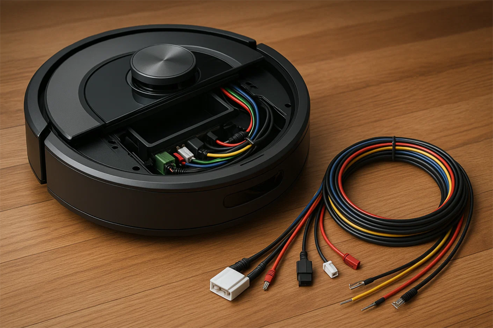
Specifying a custom cable harness for the first time can seem daunting – there are many details to consider, from electrical requirements to mechanical layout. However, by breaking the process into clear step-by-step stages, you can systematically define all necessary specifications for your custom harness assembly. This guide will walk you through each step, ensuring that by the end, you have a comprehensive set of requirements to give to a harness manufacturer. From understanding your application’s needs, to choosing materials and connectors, to final documentation, we’ll cover it all. Let’s dive into the process of turning your cable harness concept into a concrete specification.
Step 1: Define the Application Requirements
Begin by outlining what the cable harness needs to do and under what conditions. This includes the electrical requirements (such as voltage, current, signal types, and any shielding needs for data lines) and the environmental conditions (operating temperature range, exposure to moisture, chemicals, vibration, etc.).
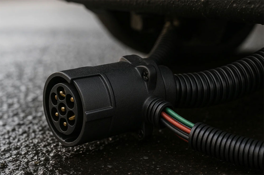
For example, ask yourself: Is this harness going inside a consumer device, or will it be in an automobile engine bay? The former might prioritize compact size and flexibility, whereas the latter requires high-temperature insulation and rugged sheathing. Also consider any industry standards your product must meet – for instance, medical devices might require ISO 13485 compliance, or military equipment might need MIL−spec components. Jot down these needs in clear terms.
At this stage, also think about safety and regulatory requirements – do you need flame-retardant materials (e.g., UL94 V−0), or RoHS compliance for all components? By capturing a detailed picture of the application, you set the foundation for all subsequent steps. As one source suggests, factors like humidity, temperature, and vibration should directly influence material selection. Essentially, Step 1 is about knowing your operating environment and functional needs, which will drive every decision that follows.
Step 2: List All Electrical Connections (Pinout)
Next, determine the pinout or wiring list for the harness – in other words, what connects to what. Enumerate all the endpoints that the harness will connect. For instance: “Connector A pin 1 goes to Connector B pin 3 (signal X), Connector A pin 2 goes to Connector C pin 5 (power +5V), etc.”
Include every wire, its source, and destination. If you have existing schematics or a block diagram of your system, use them to derive this list. Don’t forget to note any special wiring like splices (one wire splitting to two destinations), shields that need to be grounded, or twisted pair groupings for differential signals. This step is crucial because it defines the electrical topology of your harness.
Many first-time designers find it helpful to sketch a simple wiring diagram – boxes representing connectors with pin numbers, and lines for wires joining them. Remember to also specify wire functions and required colors/labels if needed (for example, you might want all ground wires to be black, all +12V wires red, etc.). Taking the time now to detail each connection will prevent confusion later and serve as the backbone of your harness specification.

Step 3: Choose Connector Types and Hardware
With your connection list in hand, decide on the connectors or terminations for each end of each wire. Often, this is dictated by the devices you’re connecting to – for instance, if your harness plugs into a PCB, you might already have a specific board connector chosen.
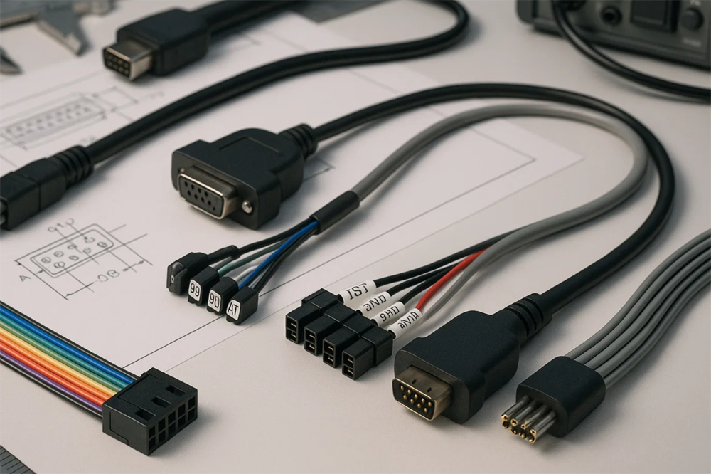
List out each connector: the make/model if you know it, number of pins, and any keying or gender info (male/female). If a wire doesn’t go into a multi-pin connector and instead ends in a ring terminal or spade lug, specify that as well (e.g., “AWG 18 wire with ring terminal for M4 screw”).
For each connector, also consider strain relief and backshells. Furthermore, if your harness requires overmolding (a molded plastic strain relief or y-branch), note that as a requirement. If you’re unsure of the best connector, you can describe the requirement (“needs a 6-pin waterproof connector, automotive grade”) and ask the manufacturer for recommendations.
Step 4: Specify Wire Types and Sizes
Now, detail the wire for each connection. Based on the current each line will carry, select an appropriate wire gauge (AWG or metric). Heavier currents need thicker wires to prevent overheating and voltage drop.
Also consider the insulation type for each wire: for example, if high flexibility is required, you might choose finely stranded wire with a silicone insulation. If any signals are sensitive to noise, you may specify shielded wires or twisted pairs.
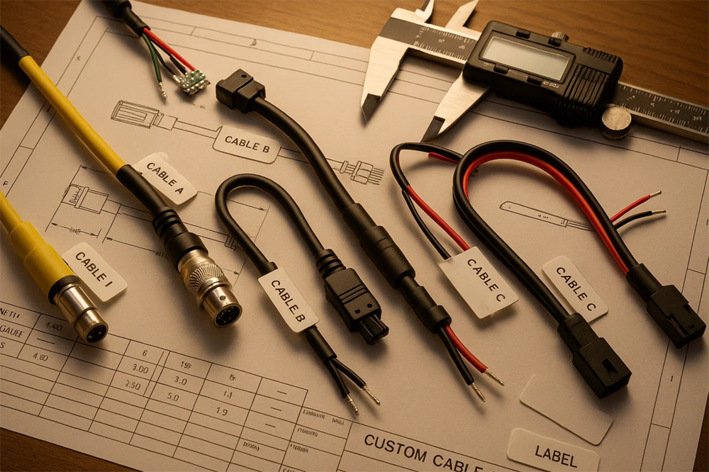
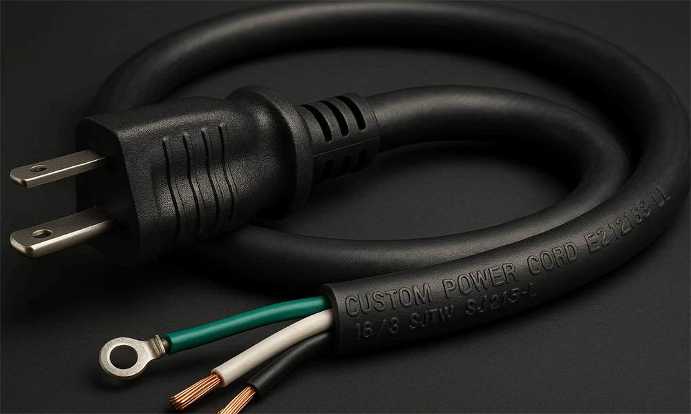
Additionally, specify wire color for each and define any required cable markings or labels. A comprehensive specification might read like: “Signal X: 24 AWG, PVC insulation, blue, twisted pair with Signal Y and overall foil shield; Power 12V: 18 AWG, XLPE insulation, red; Ground: 18 AWG, green/yellow stripe, meets UL1015.”
Step 5: Plan Routing and Dimensions
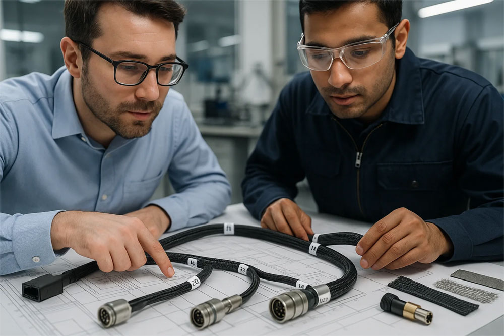
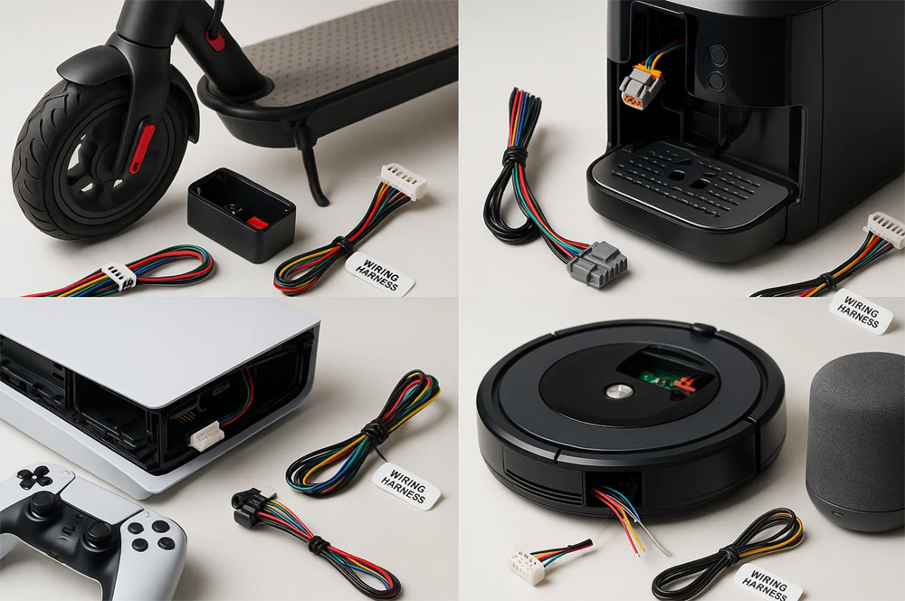
Determine the physical routing and dimensions of the harness. This includes the length of each leg or branch and where branches split. It’s often useful to create a harness drawing or at least a dimensional sketch.
Identify distances between connection points – for instance, “from Connector A to the branch point is 50 cm, then one branch goes 20 cm to Connector B, another branch 30 cm to Connector C.”
Specify any branching details, connector orientations, and if any slack or service loop is needed. Include tolerances if needed. Additionally, specify any mechanical mounting aids such as clips, clamps, or grommets that should be part of the harness. All these spatial considerations ensure that once the harness is installed, it fits perfectly.

Step 6: Include Testing and Quality Requirements
Specify how the harness should be tested and any quality standards it must meet. It’s good to explicitly state your expectations. For instance: “Harness must be continuity tested 100% and hi-pot tested at 500V DC for 1 second with no breakdown.”
Also indicate any standards the harness must comply with, for example, “assemble to IPC/WHMA−A−620 Class 2.” If you need certifications such as UL listing, this should be part of the spec.
For a first custom harness, you might also request a first article sample before full production. If so, specify that and any criteria for approval. By detailing testing and quality, you ensure that you and the manufacturer are aligned on what constitutes an acceptable harness.
Step 7: Compile Documentation and Conclude
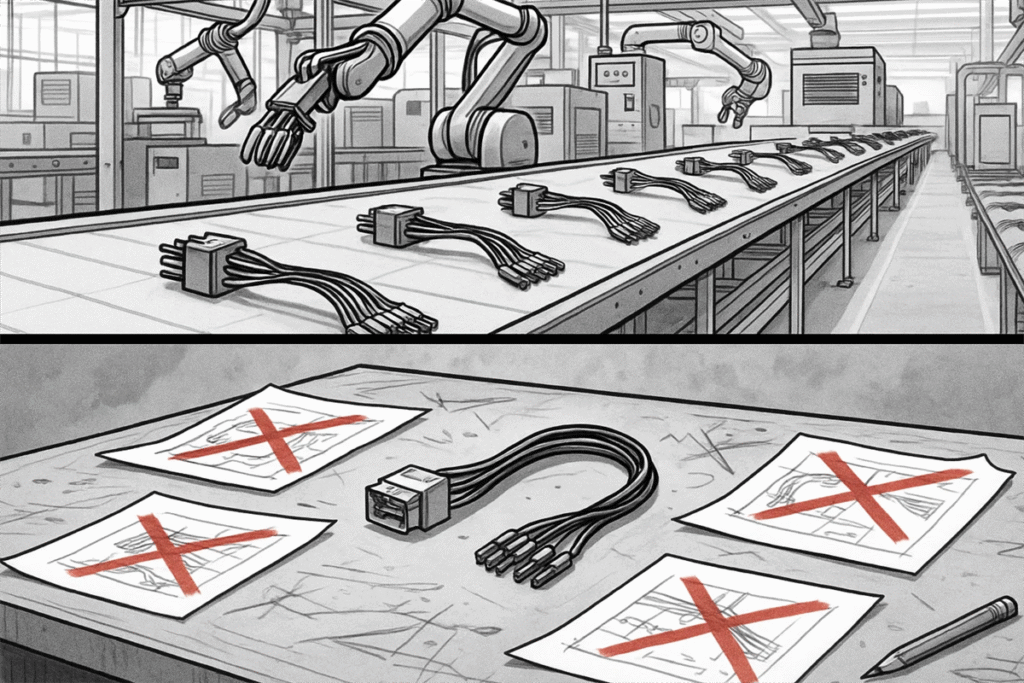
Finally, compile all the above information into a clear specification document or drawing. This should include a schematic or wiring list, a mechanical drawing with lengths, connector part numbers, wire lists, and test requirements. If there are any assembly instructions that are not obvious from the drawing, write them out.
The end result is a complete Harness Specification Package – typically consisting of a wiring diagram, a harness layout drawing, and a bill of materials. Once this is in hand, you are ready to kick off the actual manufacturing. Following these steps ensures you’ve left no stone unturned, and it transforms what can be a complex task into a manageable sequence. With a clearly specified custom cable harness, you’ll likely find the manufacturing process goes smoothly and the final product fits your needs exactly, which is the ultimate payoff for the effort invested upfront.
