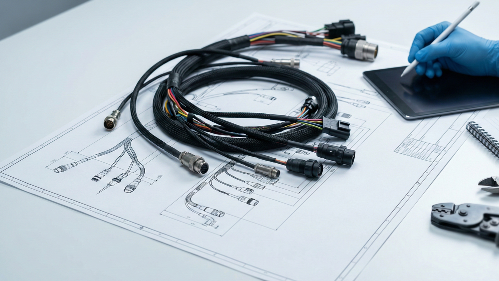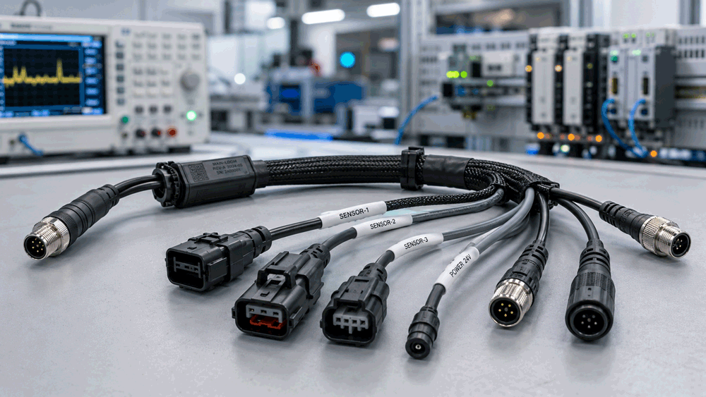
An RF cable assembly test plan should do more than prove that a cable is electrically connected. In OEM projects, the real job of the test plan is to confirm that the assembly behaves like the intended RF path under the actual product conditions. Your own RF service page already points in that direction by offering continuity, VSWR, insertion loss, and return loss data rather than stopping at generic “100% tested” language.
That distinction matters because RF cable problems are often not visible in a simple continuity check. Rohde & Schwarz notes that cable loss increases with frequency and length, and that connectors, bends, and wear can introduce reflections and added loss. In other words, an assembly can be wired correctly and still degrade the system if the RF path is not controlled and verified properly.
Table of Contents
ToggleWhy RF cable assemblies need a different test mindset
In a low-speed harness, continuity and pinout may be enough to move a prototype forward. In RF assemblies, they are only the starting point. Return loss, VSWR, insertion loss, and sometimes phase behavior determine whether the assembly is actually fit for use in the product. Keysight’s aerospace and defense RF cable test material describes cable-assembly verification in terms of VSWR, insertion loss, return loss, and phase, with TDR and distance-to-fault used to localize defects. That is a useful reminder that RF cable qualification is about transmission behavior, not just connectivity.
For OEM buyers, the practical takeaway is that a valid RF test plan should reflect the role of the assembly in the signal chain. A short internal jumper, an antenna feed, and a rugged field cable do not need exactly the same acceptance plan, even if they all use RF connectors. That is a practical inference from how VNA-based measurement vendors and your own RF service page frame RF assemblies as performance-defined rather than commodity-defined.
Start by separating prototype, pilot, and production goals
One of the most common sourcing mistakes is to treat all testing as if it happens at one stage. A better approach is to split the plan into three layers: prototype validation, pilot or first-release confirmation, and routine production checks. Your own quality and inspection pages already support this layered logic by emphasizing systematic testing and inspection rather than a single end-of-line screen.
At prototype stage, the question is whether the design concept is correct. At pilot stage, the question is whether the chosen build method is repeatable. At production stage, the question is whether the released assembly can be screened efficiently for the failure modes that are most likely to drift. That division is an inference from standard manufacturing control logic and from the distinction between detailed RF characterization tools and routine production inspection on your site.
The core RF measurements most buyers should consider
The first core measurement is continuity. Continuity still matters, because a cable assembly that fails basic point-to-point correctness cannot qualify for anything else. Your own Tests & Inspections page explicitly includes continuity as a routine verification step, so it should remain part of the RF cable baseline as well.
The second core measurement is return loss or VSWR. Keysight’s FieldFox overview calls return loss or VSWR the single most important parameter used to verify a cable-and-antenna system because it reflects power transfer efficiency. Rohde & Schwarz explains that return loss measures reflected power due to impedance mismatch, while VSWR expresses the same mismatch behavior in ratio form. For many RF cable assemblies, one of these should be in the sample-approval plan, and often both are useful depending on reporting preference.
The third core measurement is insertion loss. Rohde & Schwarz states that all coaxial cables attenuate RF signals and that insertion loss increases with length and frequency. That makes insertion loss essential whenever the assembly sits in a meaningful RF path rather than a negligible jumper role. Buyers should not assume that a cable with acceptable VSWR automatically has acceptable loss.
The fourth core measurement, when the application justifies it, is phase. Keysight’s RF coaxial cable test material includes phase alongside VSWR, insertion loss, and return loss, while Mini-Circuits explains that cable phase behavior can change with physical length, bend radius, and assembly technique. That means phase may need to be part of the plan when the product is sensitive to timing alignment, channel matching, or flex-induced phase variation.
When a VNA should be part of the plan
Rohde & Schwarz states that a VNA is the preferred tool for measuring cable loss, and NI explains that VNAs characterize passive RF devices through S-parameters. Since RF cable assemblies are passive RF components, the VNA becomes the natural tool when the buyer needs insertion loss, return loss, VSWR-related reflection behavior, or broader S-parameter confidence across a defined band.
For OEM buyers, this means a test plan should not just say “supplier to test RF performance.” It should say which RF quantities will be measured, across what band, with what acceptance target, and whether that data is required on prototypes, pilot builds, or production units. That is the difference between a measurable acceptance plan and a vague quality promise. This is a practical inference supported by the measurement-oriented framing in the cited VNA sources and your own RF service page.
What prototype approval should usually include
Prototype testing should answer the question: did we choose the right RF path? In most OEM RF projects, that means prototype approval should include continuity, dimensional and connector-configuration checks, and RF measurements such as return loss or VSWR and insertion loss over the actual operating band. If the product is phase-sensitive, phase should be reviewed as well. Keysight’s aerospace cable-test material is a good model because it treats VSWR, insertion loss, return loss, and phase as assembly-level parameters rather than optional extras.
Prototype approval should also include real routing review. Rohde & Schwarz notes that bends and connectorization can affect measured loss and reflections, so a bench measurement alone is not always enough if the installed routing is aggressive or constrained. For some products, the prototype test plan should explicitly include measurement after installation routing, not just before installation.
What pilot or first-release testing should add
Pilot testing is where the buyer should confirm that the assembly can be built repeatedly, not just once. That usually means repeating the critical RF measurements from the prototype phase, but now with attention to consistency across multiple assemblies. Your quality pages emphasize process discipline and repeated inspection logic, which fits this stage well.
This is also the stage where buyers should decide whether optional diagnostics need to be available for troubleshooting. Keysight and Anritsu both position TDR or DTF as ways to localize defects and discontinuities, rather than as primary pass/fail screening for every build. That makes them especially useful at pilot stage, engineering review, and failure analysis, even when they are not part of routine production screening.
What routine production testing should usually cover
Routine production testing should focus on what is practical to execute consistently while still controlling the main failure risks. For many RF cable programs, that means 100% continuity plus defined RF screening where the program risk justifies it. Your own RF page says VSWR, insertion loss, return loss, and continuity data can be measured per order or per cable, which suggests a flexible model: not every program needs the same production intensity, but the capability should exist when the application justifies it.
In some production environments, the buyer may choose full RF measurement on every assembly. In others, the plan may use first-article plus sampling, combined with dimensional and continuity controls, depending on program criticality and volume. That is not a one-size-fits-all rule; it is a risk decision. This is an inference from the difference between characterization-heavy RF test systems and broader production inspection practice.
When to add phase testing
Not every RF cable assembly needs phase testing, but some clearly do. Mini-Circuits explains that phase behavior is affected by physical length, bend radius, and cable-assembly technique, and its phase-stability guidance shows why some applications care about how phase shifts under flexure. Keysight’s RF cable-test material also includes phase as a measured cable parameter.
For OEM buyers, phase testing becomes more relevant when the assembly is part of matched channels, phased arrays, timing-sensitive systems, or any product where routing movement or flex can disturb signal relationships. In those projects, a test plan that stops at insertion loss and VSWR may still miss a critical system risk. That is a practical inference from the cited phase-stability sources.
When to add TDR or DTF
TDR and DTF are especially valuable when the buyer needs to locate where a mismatch or fault exists, not just confirm that one exists. Keysight notes that TDR and distance-to-fault reporting can localize cable errors for rapid diagnosis, and Anritsu positions DTF alongside return loss and VSWR for cable and antenna troubleshooting.
For OEM programs, that makes TDR or DTF particularly useful in engineering debug, supplier qualification, pilot-stage troubleshooting, and field-failure analysis. They are usually not the first test a buyer needs to require on every routine production unit, but they are extremely valuable when a project needs fault localization capability.
What buyers most often get wrong
One common mistake is writing “100% tested” without defining what the test actually covers. In RF cable work, that phrase is too vague to be meaningful. A supplier may interpret it as continuity only, while the buyer assumes it includes RF measurements. Your own site avoids that trap by naming the available checks specifically, which is exactly the better practice.
Another mistake is requiring only one RF metric. A cable can show acceptable return loss but still have too much insertion loss, or show good insertion loss but still be mismatched. That is why VSWR or return loss, insertion loss, and sometimes phase need to be considered together rather than treated as substitutes. This follows directly from how the measurement vendors define these quantities.
A third mistake is leaving routing and environment out of the plan. Rohde & Schwarz notes that bends, connectors, and wear affect measured performance, which means the installed condition can matter as much as the free cable. A test plan that ignores the real use condition may approve the wrong build.
A practical RF cable assembly test plan structure
A practical OEM test plan usually works best when written in layers.
At the prototype stage, define the operating band, measure continuity, return loss or VSWR, insertion loss, and add phase if the application needs it. Review the actual routing condition, not just the free cable.
At the pilot stage, repeat the critical RF measurements across multiple assemblies to confirm repeatability, and keep TDR or DTF available when engineering wants to localize anomalies.
At the production stage, define the routine checks explicitly, such as 100% continuity, dimensional verification where relevant, and RF screening either per cable or per order depending on risk level and program requirements. That production choice should be visible in the RFQ or release criteria, not improvised later.
Final view
A good RF cable assembly test plan is not just a quality formality. It is one of the main tools that protects the OEM from late-stage signal problems, false debugging paths, and inconsistent releases. Continuity proves the basic circuit. VSWR or return loss proves mismatch control. Insertion loss proves attenuation is acceptable. Phase, TDR, and DTF become important when the system sensitivity or troubleshooting need justifies them.
For OEM buyers, the most useful rule is simple: define the test plan as part of the product requirement, not as an afterthought after the first sample arrives. When prototype, pilot, and production checks are separated clearly, the supplier can build, test, and release the right RF assembly with much less ambiguity. Your own RF and quality pages are already aligned with that approach.
FAQ
What is the minimum test plan for an RF cable assembly
At a minimum, buyers should define continuity plus the RF measurement that matters most for the application, usually return loss or VSWR and often insertion loss across the actual operating band.
Should every RF cable assembly be tested on a VNA
Not every program needs full VNA testing on every production unit, but a VNA is the preferred tool when insertion loss, return loss, VSWR-related reflection behavior, or broader S-parameter validation is required.
When should phase be added to the test plan
Phase should be considered when the product is sensitive to cable length, bend behavior, channel matching, or flex-induced variation.
Are TDR and DTF routine production tests
Usually they are more valuable as diagnostic and troubleshooting tools than as default production screening tools, especially during engineering debug and pilot investigation.
What is the biggest test-plan mistake buyers make
One of the biggest mistakes is writing vague requirements such as “100% tested” without defining which checks are included and at which project stage they apply.
If your project depends on stable RF transmission, do not leave the acceptance plan undefined until after samples arrive. Define the operating band, the required RF metrics, and the stage at which each check applies, then let the supplier build around a measurable release plan. This article can naturally connect to your RF & SMA Cable service page as the RF-series landing point.
Related articles