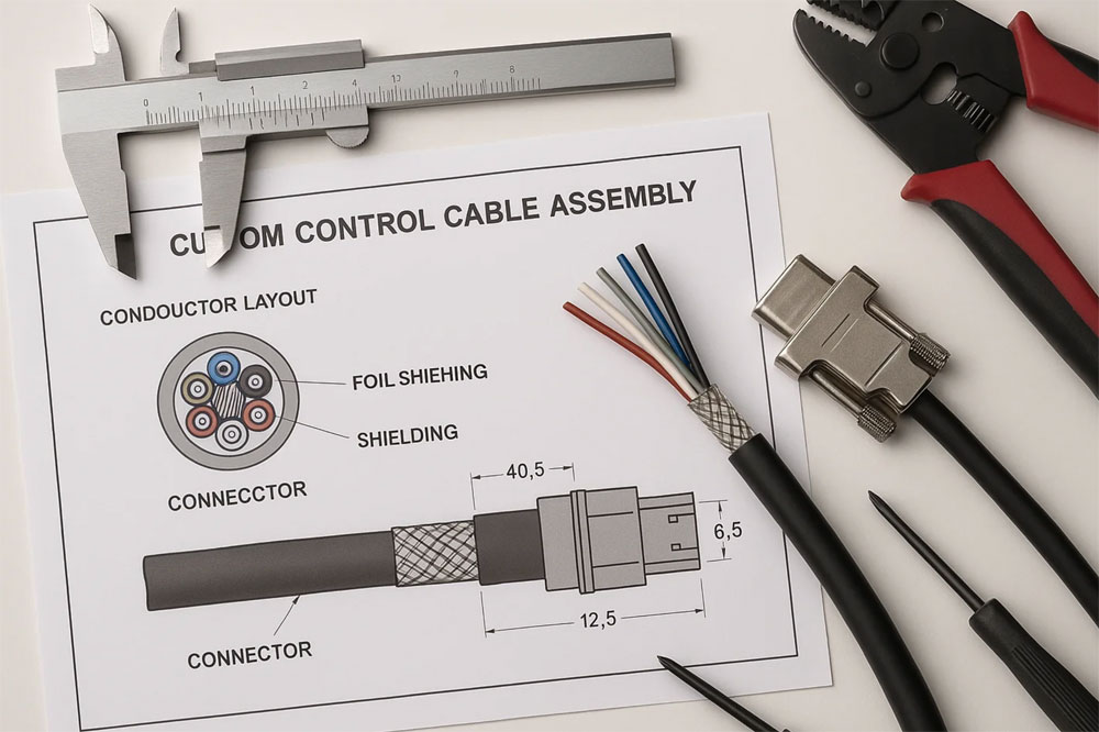
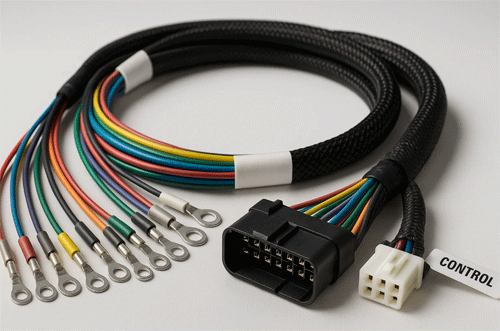
2025 Wire-Harness Design Guide: 10 Steps From Concept to Production
Table of Contents
ToggleWhy Wire Harness Design Demands a Process, Not Just a Drawing
In an age of electrification, automation, and shrinking device enclosures, a well-designed wire harness is no longer just a “back-end detail”—it’s a mission-critical subsystem. A single missing label, misrouted branch, or uncrimped terminal can bring an entire system to its knees.
And yet, too many harness designs still begin as an afterthought—hurried sketches passed to a contract manufacturer without clear specs, documentation, or testing expectations. The result? Scope creep, delays, failed prototypes, and sky-high rework rates.
This guide walks you through the 10 essential steps of wire harness design and execution in 2025, from concept to production ramp. Whether you’re a mechanical engineer routing power lines in a robot arm, or a procurement lead onboarding a new supplier, use this roadmap to build better harnesses—and partnerships.

Step 1: Define Functional Requirements, Not Just Circuits
Before you even open your CAD software or schematic tool, begin with the application’s environment and functional priorities. Ask:
-
Will the harness flex? If yes, how many bend cycles and what radius?
-
Will it be exposed to water, chemicals, UV, EMI, or vibration?
-
Are circuits carrying high current, low-voltage signals, or both?
Instead of just listing pinouts, define the operating conditions, interface constraints, and regulatory requirements. For instance, a wire harness in an autonomous farm drone must handle flex, dust ingress, pesticide spray, and maintain signal integrity over 10+ meters—all before selecting a single connector.
🎯 Tip: Create a one-page “Harness Application Profile” before schematic entry. Include environment, EMC class, IP rating, bend radius, life cycles, and inspection expectations.
Step 2: Select the Right Components (and Freeze the BOM Early)
Component selection drives everything from cost to compliance. In 2025, buyers should prioritize:
-
UL/CSA recognized wire and terminals, to streamline regulatory audits
-
Halogen-free, low-outgassing jackets for medical and aerospace harnesses
-
Tin-plated copper vs. silver-plated for anti-corrosion in high-humidity regions
-
Locking or latching connectors for high-vibration environments
-
Connector modularity for family harnesses to reduce SKU count
Once selected, freeze the component BOM early in the design phase. Last-minute part substitutions often cause tooling incompatibilities or re-validation delays.
🎯 Tip: Use supplier-preferred parts lists (PPLs) and pre-certified kits to reduce sourcing lead times and certification friction.
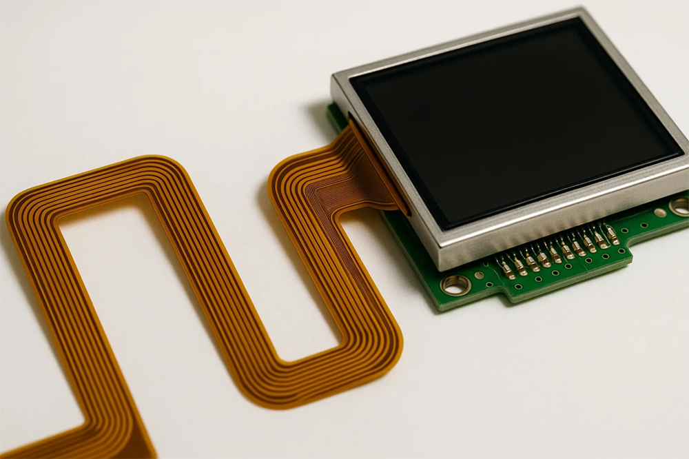
Step 3: Draft Schematic + Functional Block Diagram
At this stage, translate electrical intent into signal paths and logical groupings.
-
Use symbols and standards per IPC-D-310 or IEEE 315.
-
Organize circuits by power, control, data, and shielding needs.
-
Include inline fuses, resistors, capacitors, or relays if required.
-
Don’t forget reference designators for wire labels.
🎯 Tip: Split your schematic into signal blocks to match your routing strategy. It’s easier for harness engineers to plan branches when circuits are grouped by location.
Step 4: Plan 3D Routing with Realistic Bend Radii
In 2025, wire harnesses are rarely designed in 2D alone. Use 3D CAD harnessing tools (e.g., SolidWorks Electrical, Zuken E3.series, Siemens Capital) to:
-
Route cables through clips, grommets, strain reliefs
-
Ensure bend radii ≥ 10x cable OD for flexing sections
-
Avoid tight 90° turns and sharp chassis edges
-
Simulate length tolerances for motion axes or hinged doors
This step avoids “design-to-fit” failures, where the actual harness binds or stretches due to enclosure interference or misestimated slack.
🎯 Tip: Use digital twins of your enclosure to test space claims before committing to any cut-lengths or branch-outs.
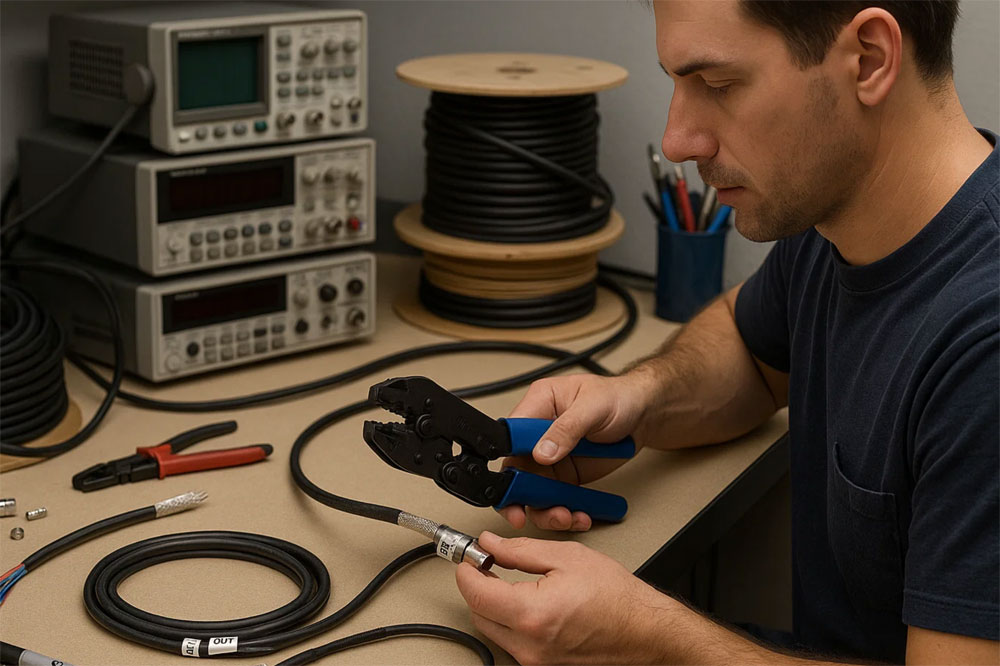
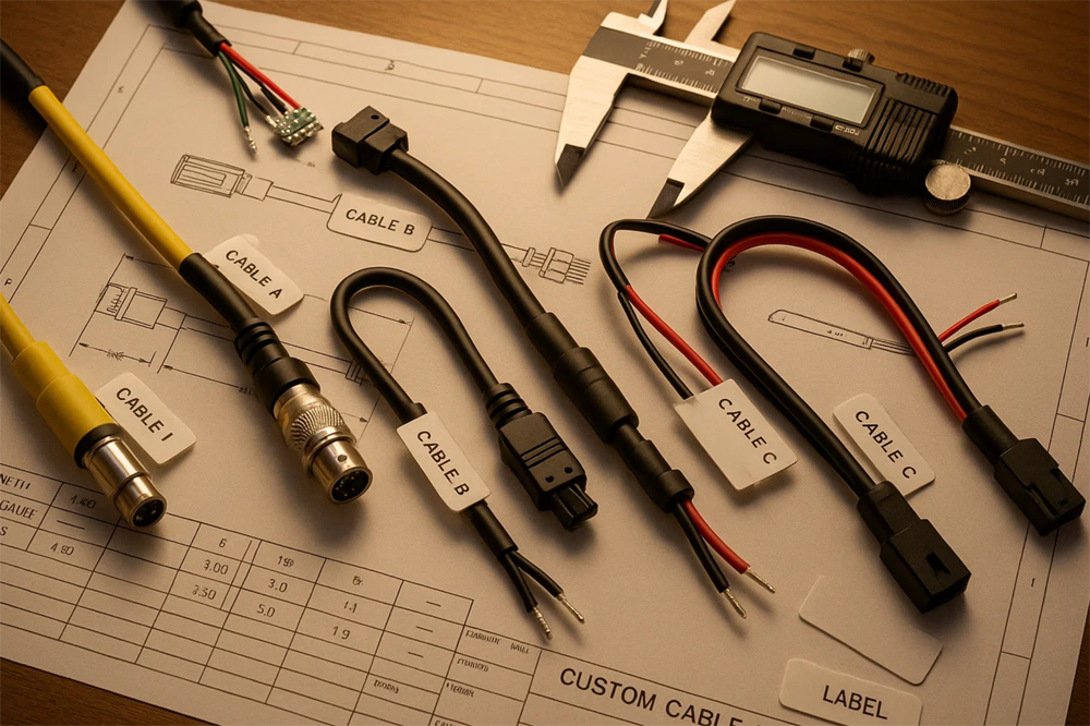
Step 5: Create a Full Harness Drawing With Build Specifications
This is your handoff to production. The harness drawing should include:
-
Reference schematic and cable harness number
-
Wire type, AWG, color, length, label ID for each run
-
Branching logic (Y-splits, breakouts, tap-ins)
-
Connector PN, orientation, pinout, mating parts
-
Assembly notes for sleeving, braiding, heat-shrink, or potting
-
Torque specs for threaded terminals
-
Testing requirements (e.g., continuity, HiPot, pull-test)
🎯 Tip: Use color-coded layers for signal types, or include a mini wire-list table as an inset on the drawing.
Step 6: Prototype the Harness and Validate Fit, Function, and Handling
Before greenlighting production, build a physical prototype or 3D-printed harness fixture to validate:
-
Routing through chassis or mechanical interface
-
Label visibility and connector reach
-
Operator ergonomics during installation
-
Fit under real-world flex or vibration cycles
Harnesses that “fit on paper” often bind, sag, or twist in real use. Real-world trials reveal routing faults, torque access issues, or signal degradation due to EMI or poor grounding.
🎯 Tip: Use low-cost sample builds (even partial harnesses) during field testing to collect design feedback before full-tool release.

Step 7: Define and Document the Test Plan
In 2025, quality expectations go beyond continuity. Your test plan should define:
-
Continuity test (open/short detection)
-
HiPot test (insulation breakdown voltage)
-
Pull-force test per IPC/WHMA-A-620E
-
Crimp height or cross-section validation
-
Flex or vibration testing for dynamic applications
-
Ingress protection test if ≥ IP54 claimed
Each test step should list method, tool, pass/fail threshold, and traceability. Good suppliers will deliver test reports per lot, and archive failure data for 3–5 years.
🎯 Tip: Add QR codes to test sheets or harness labels that link to digital traceability records.
Step 8: Establish the Assembly Work Instructions (WI)
For consistent quality across batches, develop clear, visual WIs:
-
Include photos of crimping, sleeving, tie points
-
Define tooling by part number (e.g., AMP 91523-1)
-
Annotate work zones with operator checks
-
Flag critical-to-quality (CTQ) steps
-
Use IPC Class references for accept/reject calls
Modern manufacturers use tablets at workstations with PDF/interactive WI displays. Keeping these updated reduces scrap and training time.
🎯 Tip: Use red/green icons or “Go/No-Go” photos to make WIs instantly scannable for operators.
Step 9: Set Supplier Expectations: Lead Time, MOQ, Certifications
Beyond technical drawings, your sourcing doc should define:
-
Target lead time (e.g., 2 weeks for repeat orders, 4 for new builds)
-
MOQ: What’s the supplier’s min? Can they do 50 pcs for pilot?
-
Quality level (IPC Class 2 or 3)
-
Required certifications: UL, ISO 9001, IATF 16949 (for auto), FDA (med)
-
Labeling + packaging instructions
-
Drop-test or transit simulation if shipping internationally
🎯 Tip: Use a “Supplier Readiness Checklist” to speed onboarding and prevent quote mismatches.
Step 10: Launch With Pilot Run and Iterate
Run a pilot batch of 50–200 units, then:
-
Measure yield, cycle time, scrap
-
Review operator feedback
-
Check install time and error rate at customer site
-
Conduct failure analysis on returns, if any
-
Validate test-data traceability and lot-tracking
This “soft launch” phase is where minor changes—label size, terminal orientation, test jig tweaks—create big downstream savings.
🎯 Tip: Use pilot feedback to adjust drawings, WIs, and test limits before greenlighting mass production.
Conclusion – Good Harnesses Start With Good Processes
In 2025, wire harness design is no longer just a back-office task—it’s a strategic discipline. The best-performing products in EVs, drones, robots, and medical devices all rely on reliable, scalable, testable harnesses—and those start with:
-
Clear requirements
-
Right components
-
Realistic 3D routing
-
Build-ready drawings
-
Controlled test and trace plans
If your harnesses are causing delays, noise, or failures—it’s not just the cable. It’s the process. Use these 10 steps to raise your design maturity and supplier coordination.
CTA – Need Help Turning Concepts Into Production-Ready Harnesses?
Infinite Possibilities Technology helps OEMs design, prototype, and manufacture IPC-compliant harnesses—starting at just 50 pcs, and scaling to 50,000+.
✔ Free DFM audit
✔ IPC/WHMA-A-620 Class 2 & 3 support
✔ UL, CE, and automotive readiness
✔ Transparent lead times and full lot traceability
📩 [Contact Us Now] – Turn your next drawing into a tested, trusted solution.

